The Arduino Uno has six PWM ports, but not every micro-controller has this many. In this tutorial I will show you how to implement software PWM. By using a potentiometer to input a desired level we can then control the brightness of an LED on another pin.
First of all I’m going to assume you know what PWM is. If you don’t, Wikipedia is your friend. Basically PWM uses a digital port to approximate an analog port. It does this by setting a percentage of a set cycle to HIGH, and the rest to LOW. When this repeats really fast (say 10,000 times a second) the voltage averages out to somewhere in between HIGH and LOW. You can set the voltage by determining how much of the cycle is HIGH and how much is LOW (the duty cycle). Ok, carry on!
The circuit setup is pretty basic. Simply set up a potentiometer between +5v and GND, and connect the wiper (the middle pin) to an analog input - in this case analog pin 1 on the Arduino. An LED is then connected to a digital output pin (digital pin 8), and you can see on the schematic that it is placed after two Resistance - Capacitor (RC) filters. If you would like to know more about RC filters, then I recommend you look at EEVBlog http://www.eevblog.com/2011/12/07/eevblog-225-lab-power-supply-design-part-4-pwm-control/ - the post that inspired this tutorial! Dave gives quite a bit of information on RC filters on this post and shows how to use LTSpice to simulate. I highly recommend you have a look at this video!
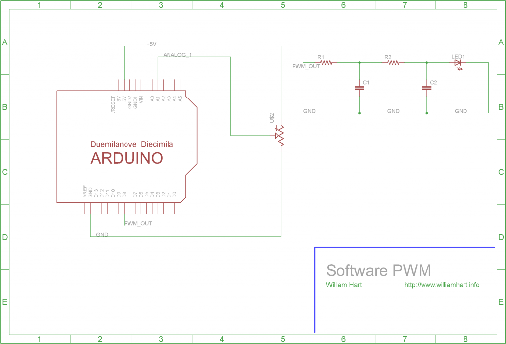
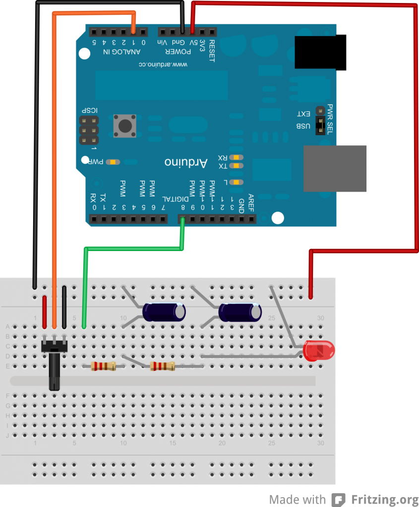
You may think that my capacitor/resistor values area bit strange in the schematic, well thats because I just grabbed what was at the top of my bits box! If you were doing this in “production” you would take a lot more care selecting your values - again, have a look at Dave’s post for more information. You can see the circuit setup in Fritzing below.
And then the following code was used:
/**************************************************************/
/* POT controlled software PWM                                */
/*                                                            */
/* Code written by William Hart, 2011                         */
/* http://www.williamhart.info                                */
/*                                                            */
/* This is a very simple circuit which uses a potentiometer   */
/* to set an analog input and then uses this input to drive a */
/* PWM signal using a standard (non-PWM) port on the Arduino. */
/**************************************************************/

//Serial.println(microsecondsToClockCycles(1)); // gives a result of 16 clock cycles per microsecond

// define pins
#define ADJ_PIN 1 // Adjustment pin is analog 0
#define PWM_PIN 8 // PWM output pin is digital 8

// setup PWM values
#define PWM_FREQ 300 // PWM Hz, must be greater than 60Hz to avoid delayMicroseconds issues
#define MAX_V 5.00 // the maximum voltage we can output

long cycle_length;
float v_out;
float duty_cycle;
int on_time;
int off_time;

void setup()
{
  // start up serial for debugging
  Serial.begin(9600);

  // set pin states
  pinMode(ADJ_PIN, INPUT);
  pinMode(PWM_PIN, OUTPUT);
  digitalWrite(PWM_PIN, LOW);

  // calculate the cycle length
  cycle_length = 1000000/PWM_FREQ; // the length of a single cycle of the PWM signal
}

void loop()
{
  // read in the potentiometer value
  int val = analogRead(ADJ_PIN);

  // map the pot value to the PWM value - 0-5V, to two decimal places
  v_out = map(val, 0,1024, 0, 500);
  duty_cycle = (v_out/100) / MAX_V; // work out what percentage of the PWM cycle we should set high
  on_time = duty_cycle * cycle_length;
  off_time = cycle_length - on_time;

  // now set high, then delay for the duty_cycle percentage * cycle_length
  if(on_time > 0)
  {
    digitalWrite(PWM_PIN, HIGH);
    delayMicroseconds(on_time);
  }

  digitalWrite(PWM_PIN, LOW);
  delayMicroseconds(off_time);
}
Phew, what a lump of code! Once you break it down though, its quite simple. The basic principle is this:
- Setup : Work out how long our cycle is
- Loop:
- Read the potentiometer value and determine the output voltage we would like
- Set the digital port high for the correct portion of the cycle
- Set the digital port LOW for the remainder of the cycle
I use the delayMicroseconds() function from Arduino to time the PWM cycle,
however this has the limitation of being able to delay for a maximum of around
16,000 microseconds. This means that we can’t set value below 61Hz for our PWM
frequency. This could be remedied by a more intelligent use of delay(),
however I leave this as an exercise for you!