You can never have enough pins on your micro-controller, right? Plug in an LCD display, a couple of status LEDs and a few sensors and you are already up to more pins than most entry level micros. Sure, you can plug in a shift register like the 8-bit 74HC595, but is that the only way?
One less common way is to use a technique called Charlieplexing. You can Charlieplex a bunch of LEDs from a few Arduino ports, and save those precious ports for something exciting! In the following tutorial, I’m going to show you how to use an Arduino and this charlieplexing technique to use 3 output pins to control 6 LEDs.
What is Charlieplexing?
If you have a quick scan of the charlieplex Wiki entry, you can see that this technique allows you to drive $n^2 - n$ LEDs using only n Arduino pins. What does that mean? Well in our case we have 3 pins, which will allow us to drive $3^2 - 3 = 6$ LEDs. This simple technique basically uses the properties of LEDs being diodes, and therefore only allowing current (within limits of course) to pass in one direction.
How do I Charlieplex?
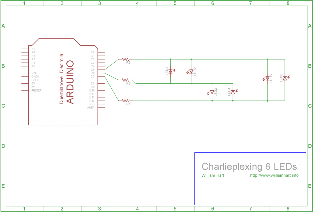
A simple LED charlieplex circuit can be setup using my Arduino Uno like the circuit diagram below.
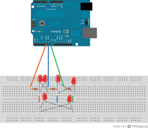
Plugging into my breadboard gives the following physical circuit - its a bit messy but take your time and you should see the pattern!
Basically, the circuit involves setting up three Arduino pins. For each pair of pins we put two LEDs between them, with on LED being placed in each direction. (Remember LEDs have an anode and a cathode, usually the longer leg being the + leg or the anode). The clever bit about the charlieplex technique is recognising that we can set pins (on the Arduino as well) to one of three states:
- HIGH - usually +5v
- LOW - usually 0v
- High Impedence - disconnected
Lets use an example. Have a look at the circuit diagram above. First we set the Arduino pin 5 to HIGH, pin 6 to High Impedance and pin 7 to LOW (more on how we do this later). Now, lets follow the current through from pin 5 (note we are talking about conventional current, not electron flow). We can see that there are four LEDs connected to this pin - the first two linked to pin 6 and the last two linked to pin 7. We can ignore two of these LEDs as they are the “wrong way around” and blocking current flow.
Now recall that we set pin 6 to this high impedance state, which means it is in effect disconnected. As pin 7 is set to low, we can see that current will flow along from pin 5, then through the LED connected between pin 5 and pin 7. (This is the 5th LED along). In this same fashion we can then set one of each of the three pins to high, low and high impedance to control which LED is switched on.
I have provided some sample Arduino code below to show this in action. Note that the Arduino reference says
Arduino (Atmega) pins configured as
INPUTwithpinMode()are said to be in a high-impedance state.
This means we can just set a pin to input mode using pinMode(pin_number, INPUT); and it will count as disconnected.
I used a form of Charlieplexing on my PIC Countdown Timer to light up three sets of two LEDs using only four pins. You can see the schematic and some photos through the link.
/**************************************/
/* Charlieplexing 6 LEDs with 3 Pins  */
/*                                    */
/* Code written by William Hart, 2011 */
/* http://www.williamhart.info        */
/*                                    */
/* Uses 3 pins to power a network of  */
/* 6 LEDs using the charlieplexing    */
/* technique.                         */
/**************************************/

#define LED_A 5
#define LED_B 6
#define LED_C 7

void setup()
{
  // first set all pins to input, or high impedance
  // (not strictly necessary as all pins are inputs by default)
  pinMode(LED_A, INPUT);
  pinMode(LED_B, INPUT);
  pinMode(LED_C, INPUT);
}

void loop()
{
  // run through a sample loop, lighting each LED

  // in turn and holding for half a second.
  set_pins(LED_A, LED_B);
  delay(100);

  set_pins(LED_B, LED_A);
  delay(100);

  set_pins(LED_C, LED_A);
  delay(100);

  set_pins(LED_A, LED_C);
  delay(100);

  set_pins(LED_B, LED_C);
  delay(100);

  set_pins(LED_C, LED_B);
  delay(100);
}

void set_pins(int high_pin, int low_pin)
{
  // reset all the pins
  reset_pins();

  // set the high and low pins to output
  pinMode(high_pin, OUTPUT);
  pinMode(low_pin, OUTPUT);

  // set high pin to logic high, low to logic low
  digitalWrite(high_pin, HIGH);
  digitalWrite(low_pin,LOW);
}

void reset_pins()
{
  // start by ensuring all pins are at input and low
  pinMode(LED_A, INPUT);
  pinMode(LED_B, INPUT);
  pinMode(LED_C, INPUT);

  digitalWrite(LED_A, LOW);
  digitalWrite(LED_B, LOW);
  digitalWrite(LED_C, LOW);
}